Robotic Dog — Full-Stack Autonomous Robot: Computer Vision, NLP, and Mechatronics
Maedcore builds a full-stack autonomous robot: MobileNetV2 vision on an NVIDIA Jetson Nano with ROS, a quantized Llama model, servos, and a 3D-printed chassis.

Written by Eduardo Fuentevilla Blanco
Robotics Engineer at Maedcore · Robotics Engineer LinkedIn ↗
Full-Stack Autonomous Robot: Computer Vision, NLP, and Mechatronics
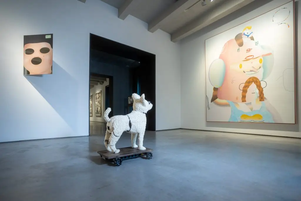
Executive summary: Maedcore designed and built a complete autonomous mobile robot from the ground up: a dual-camera computer vision system (MobileNetV2 detection on an NVIDIA Jetson Nano running ROS) for object detection and targeting, an NLP language model — a quantized Llama served from a connected server — that generates natural-language output, a 15-servo actuation system for locomotion and expression, a 3D-printed chassis manufactured across 22 parts, and a mini thermal printer for physical output delivery. The project covers the full robotics stack — mechanical design, electronics wiring, embedded systems integration, and AI code development — in a single end-to-end build. The deployment application is autonomous art critique; the engineering stack is applicable to inspection robots, autonomous navigation platforms, and human-robot collaboration systems.
Client: Built by Maedcore as engineering partner for artist Mario Klingemann, commissioned under the patronage of Espacio SOLO and Onkaos.
The Engineering Scope
This project required Maedcore to operate across five simultaneous engineering disciplines:
- Mechanical design — CAD modelling of a quadruped chassis optimised for 3D printability, internal component packaging, and maintenance access.
- 3D manufacturing — 22-part print job, with individual parts requiring up to 36 hours of print time, followed by post-processing and assembly.
- Electronics integration — full wiring of a 15-servo actuation system, dual cameras, audio hardware, thermal printer, cooling, and power management.
- Embedded systems — real-time OS configuration, task scheduling for concurrent computer vision and locomotion control, sensor-to-actuator latency management.
- AI development — computer vision model for object detection and targeting, NLP pipeline for natural-language output generation, integration of both into a single operational loop.
The key constraint across all five disciplines: every component must fit within a sealed chassis, with no external wiring or exposed hardware.
Stage 1: Mechanical Design
The mechanical design phase established the constraints for everything downstream:
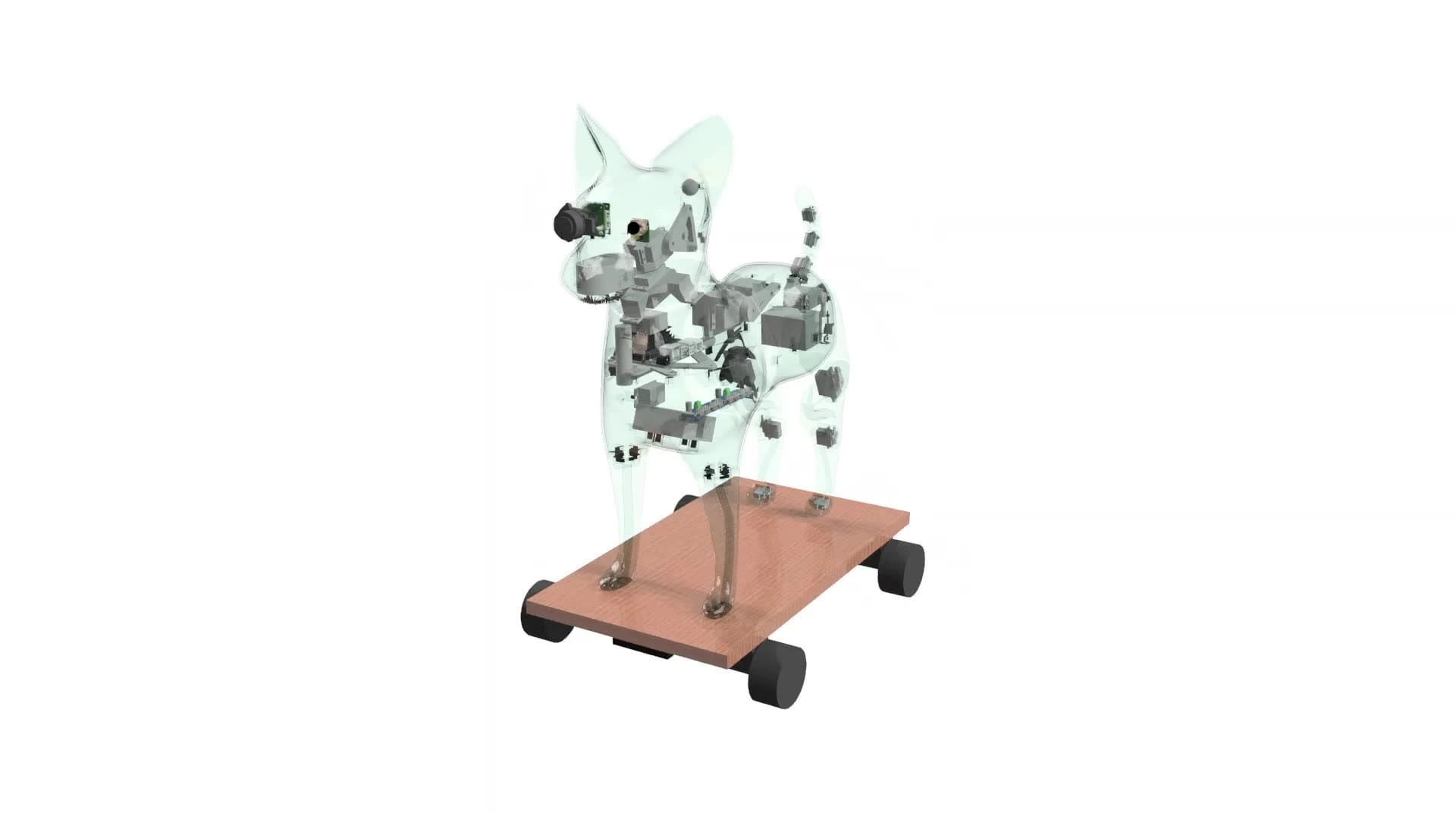
Conceptual CAD model — overall geometry, joint positions, and movement envelope. The quadruped configuration was chosen for stability on irregular surfaces and for the range of expressive poses achievable through coordinated servo actuation.
Detailed component layout — every electronic component was modelled into the chassis at this stage. Decisions made here determined:
- Internal airflow paths for the cooling fan.
- Cable routing from the 15 servos to the central controller.
- Camera mounting geometry for the required field-of-view angles.
- Thermal printer placement relative to the output slot in the body.
Manufacturing split — the chassis was divided into 22 printable parts, each sized to fit within the print volume while minimising support material and post-processing time.
Stage 2: 3D Manufacturing and Assembly
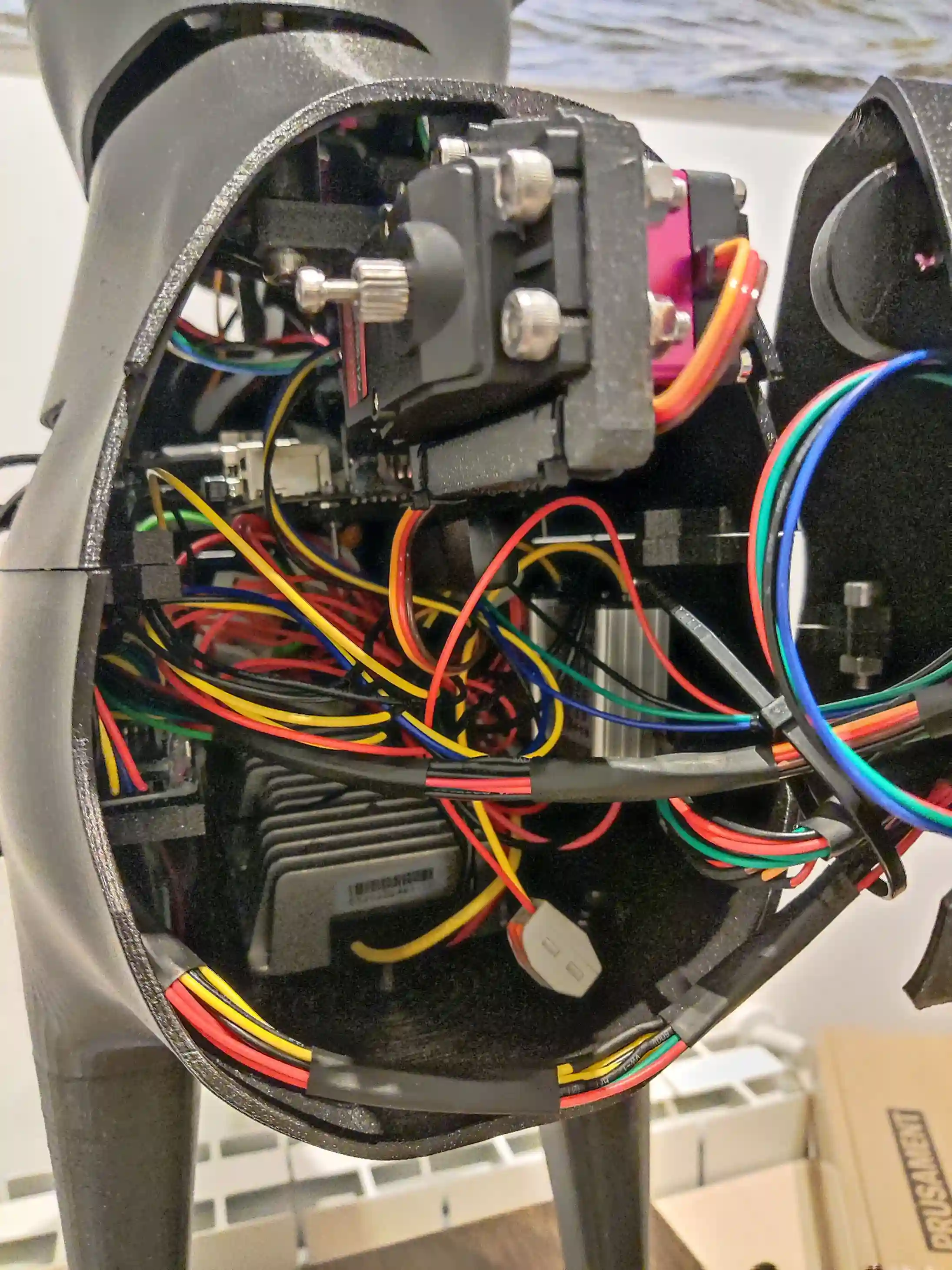
The 22 chassis parts were printed in-house on a Prusa MK3, sequentially, with the largest requiring up to 36 hours per part. Print parameters (infill density, wall count, layer height) were tuned per part based on structural loading requirements — structural members use higher infill than enclosure panels.
Assembly proceeded in three sub-stages:
- Head assembly — integrating the wide-angle camera, autofocus camera, speaker, and microphone into the head unit before closing the enclosure.
- Body assembly — routing all cabling from the servo harness, power management board, and thermal printer into the main chassis before closing.
- Limb assembly — attaching and calibrating the 15 servos for the legs, tail, and head, with endpoint position verification before software integration.
Stage 3: Electronics and Wiring
The electronics integration required coordinating 14 distinct hardware components:
| Component | Function |
|---|---|
| Wide-angle camera | Scene detection — identifies objects in the environment |
| Autofocus camera | Target capture — high-resolution image acquisition of selected objects |
| NVIDIA Jetson Nano (on-board) | Runs the MobileNetV2 detection model and the locomotion controller under ROS |
| 15 servos | Leg joints (12), tail (1), head pan (1), head tilt (1) |
| Internal cooling fan | Thermal management for CPU under inference load |
| Speaker | Audio output for NLP-generated speech |
| Microphone | Environmental audio input and interaction detection |
| Mini thermal printer | Physical output — prints generated text on paper |
| Communication antenna | Wireless link to the language-model server and live remote monitoring from a computer |
| Power management board | Voltage regulation and battery management |
| 4 wheel drive motors | Autonomous locomotion on flat surfaces |
All wiring was completed before the chassis was closed — no post-assembly access to internal cabling.
Stage 4: AI Integration
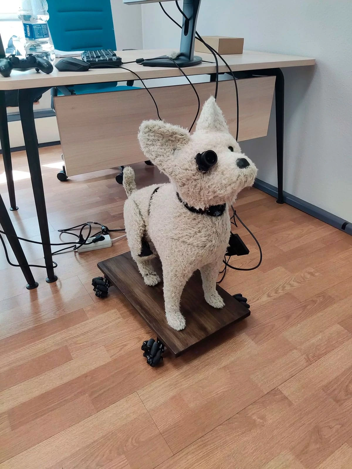
The AI system operates as a two-stage sequential pipeline:
Stage A — Object Detection and Navigation
The wide-angle camera feeds a MobileNetV2 object-detection model — chosen for its accuracy-to-latency balance on constrained hardware — running on an NVIDIA Jetson Nano under ROS. It detects and classifies objects within the robot’s field of view. When a valid target is identified, the system:
- Calculates the angular offset between the robot’s current heading and the target.
- Transmits navigation commands to the locomotion controller.
- Drives the robot forward, steering toward the target.
- Halts when the target is within the autofocus camera’s optimal capture range.
The navigation loop runs at 10 Hz, updating the heading correction on every frame.
Stage B — Analysis and Output Generation
Once positioned, the autofocus camera captures a high-resolution image of the target. Language generation is too heavy to run on the battery-constrained robot, so this stage is offloaded:
- The captured image and its extracted visual features are sent over the wireless link to a connected server.
- The server runs a quantized Llama language model — quantization shrinks the model’s memory footprint so it runs on modest server hardware — which generates a natural-language description of the target.
- The generated text is returned to the robot and routed to the speaker for audio output.
- Simultaneously, the thermal printer produces a paper printout of the output.
The two-stage pipeline — detection → navigation → capture → generate — runs without human intervention from initial detection to final output.
Compute Architecture: Edge Perception + Server-Side Language Model
The robot uses a hybrid edge/server architecture. Perception and control stay on-board for low latency — the Jetson Nano runs MobileNetV2 detection and the navigation loop locally under ROS — while the heavier language generation runs off-board on a connected server hosting the quantized Llama model. The two communicate over a wireless link, which also lets an operator monitor the robot live from a computer: camera feed, detection state, and locomotion status. The split keeps the robot responsive and within its power budget while still producing rich natural-language output.
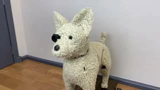
Demonstration Videos

Performance Metrics
| Metric | Result |
|---|---|
| Object detection accuracy | High — validated across multiple target types and lighting conditions |
| Navigation-to-target time | ~15 seconds from detection to optimal capture position |
| NLP output generation | < 3 seconds from image capture to audio output |
| Servo coordination | 15 servos operating in coordinated gait patterns without actuation conflicts |
| Battery autonomy | ~2 hours of autonomous operation per charge |
| Remote monitoring | Live camera feed and status viewable from a computer over the wireless link |
Technology Applications
The engineering disciplines exercised in this project map directly to industrial robotics applications:
Autonomous inspection. The perception-navigation-capture pipeline — detect target, move to optimal position, capture high-resolution data — is the core architecture for automated inspection robots in manufacturing, infrastructure, and energy.
Industrial navigation. The multi-servo locomotion system and real-time CV-driven navigation loop scale to warehouse AGVs and assembly-line robots operating in unstructured environments.
Human-robot collaboration. The audio I/O system and NLP output layer are the foundation for robots that communicate their status, findings, and actions to human operators in natural language.
Computer vision quality control. The two-stage CV pipeline (wide-angle detection + autofocus capture) is directly applicable to automated visual inspection systems for defect detection on production lines.
Technologies Used
Project developed with: Autonomous Robotics — Computer Vision (MobileNetV2) — NLP (quantized Llama) — ROS — NVIDIA Jetson Nano — Embedded Systems — 3D Design and Manufacturing (Prusa MK3) — Servo Control — Mechatronics — Edge AI Inference
Building an Autonomous Robot or Computer Vision System?
This project demonstrates that Maedcore can take a complex robotics system from CAD design to fully autonomous operation — integrating mechanical engineering, electronics, embedded systems, and AI in a single build. If you have a robotics, inspection, or computer vision requirement, request a technical quote.
Request Robotics Quote | View Mechatronics Services | View AI Services
Further Reading
Related reading: the most impactful AI applications for business in 2026 and machinery safety for equipment manufacturers.
About the Author
Eduardo Fuentevilla Blanco
Robotics Engineer
For over a decade, I have been driven by a single mission: leveraging AI and robotics to build a world of automated production. I believe that by creating self-sufficient systems, we can empower people to refocus on what truly matters—their families and their passions. My expertise spans from winning prestigious European startup competitions to architecting complex, integrated hardware and software projects. I specialize in bridging the gap between today's industrial challenges and tomorrow's autonomous solutions.
Ready to transform your company?
Book a free 30-minute meeting with an engineer.