IoT Wearable Product Design: GPS Enclosure Engineering and DFM
Maedcore delivers complete IoT wearable design: GPS integration, DFM-optimised enclosure modelling, multi-attachment form factor, and manufacturing renders.

Written by Eduardo Fuentevilla Blanco
Robotics Engineer at Maedcore · Robotics Engineer LinkedIn ↗
IoT Wearable Product Design: GPS Enclosure Engineering and DFM
Executive summary: Maedcore delivered the complete product design lifecycle for a GPS-enabled IoT wearable device: from functional specification and component placement planning through to DFM-optimised 3D enclosure modelling, multi-attachment form factor development, and photorealistic renders for manufacturing handoff. The engineering scope covered GPS module integration constraints (antenna clearance, ground plane requirements, RF shielding), thermal management within a sealed plastic enclosure, multi-attachment-point mechanical design (keyring, clip, bag attachment), and material specification for injection moulding. The client was Calmtag, a Spanish IoT startup. The methodology and deliverables — CAD files, exploded assembly renders, material and colour specifications, manufacturing-ready documentation — are the same Maedcore applies to industrial sensor housings, ruggedised field devices, and embedded hardware enclosures across any sector.
The Engineering Brief
Calmtag required a GPS tracking device in a form factor that people would actually carry without stigma or inconvenience. The key engineering constraints:
RF performance inside a consumer enclosure. GPS modules have strict antenna clearance requirements — minimum distances from metal components, ground planes, and enclosure walls — that directly constrain component layout and housing geometry. Violating these constraints degrades GPS fix accuracy and time-to-first-fix.
Sealed, compact housing for a multi-component system. The device contains a GPS module, cellular communication hardware, battery, and power management circuitry. All must fit within a sealed housing small enough to attach to a keyring or backpack clip — with no external cabling or exposed connectors.
Multi-attachment form factor. The device must attach reliably to a keyring, a backpack zipper, a bag strap, and a clothing clip — four distinct mechanical interfaces — without any of the four requiring a different housing variant. The attachment system must be reversible (user-attachable without tools) and secure enough that the device doesn’t detach during normal use.
DFM readiness. The final design deliverable must be manufacturable via injection moulding without design changes. Wall thickness uniformity, draft angles, undercut avoidance, and gate placement must all be resolved at the CAD stage.
Phase 1: Functional Specification and Component Layout
The design process began with a detailed component specification:
- GPS module selected for compact footprint (12 × 16 mm) and integrated antenna support.
- Battery capacity sized for 72-hour continuous tracking within the target form factor volume.
- Cellular module positioned for optimal antenna performance — away from the GPS module to minimise RF interference.
- Power management IC placed adjacent to the battery with short trace routing requirements.
With all components specified, Maedcore produced the first CAD model as a component layout study — no enclosure geometry, just component blocks with their clearance envelopes. This layout study defined the minimum internal volume of the enclosure and the spatial constraints on every subsequent design decision.
Phase 2: Enclosure Geometry Development
Initial Concepts
Three enclosure concepts were developed in parallel, exploring different form language approaches:
- Organic — continuous curved surfaces, no sharp edges, pebble-like cross-section.
- Angular — flat faces with chamfered transitions, strong visual identity, easier to grip.
- Hybrid — organic primary surfaces with angular accent details for brand identity.
Each concept was evaluated against the attachment system requirements, the DFM constraints, and the component layout envelope.
Iterative Refinement
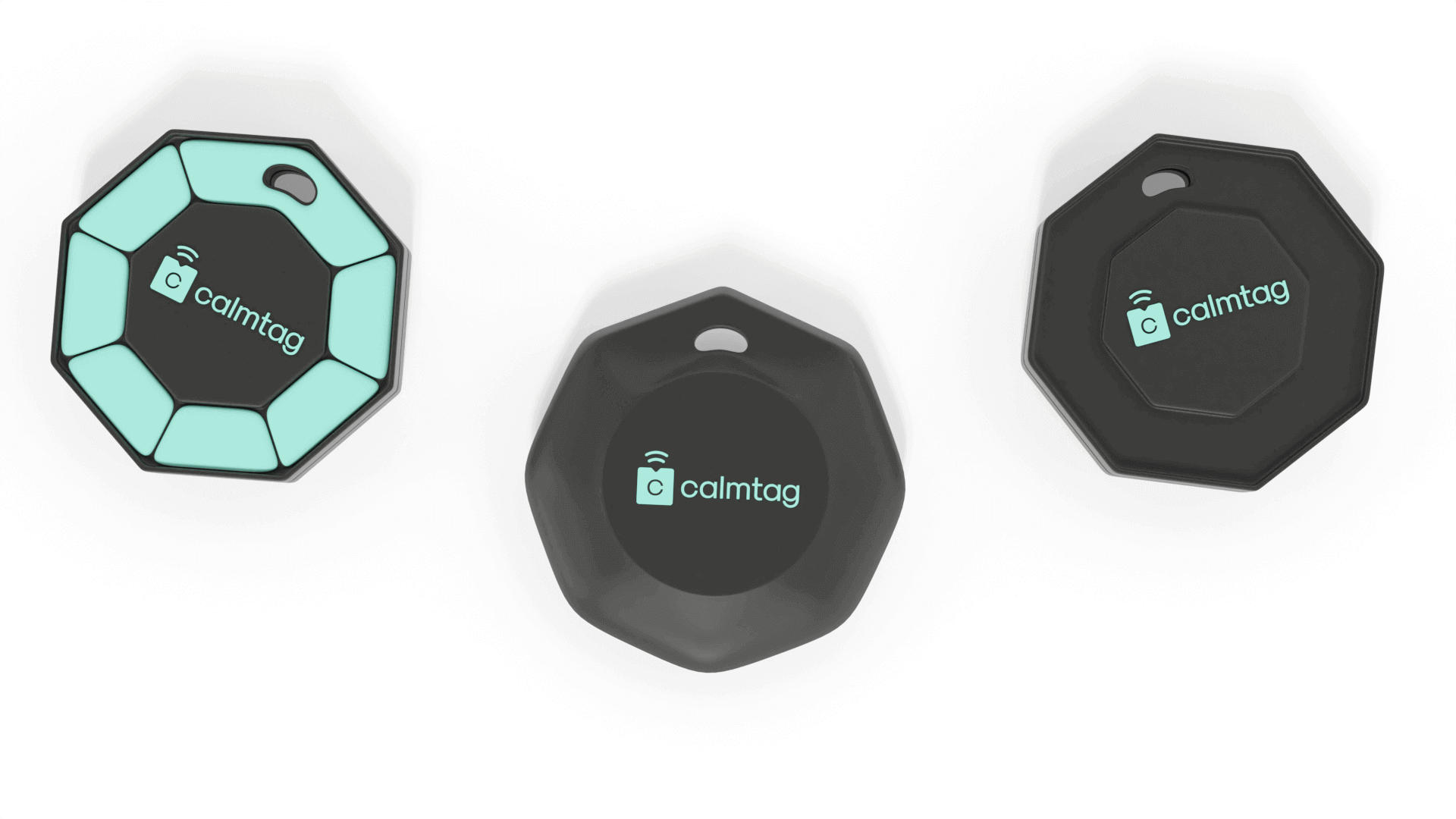
Three full design iterations were completed, each addressing specific issues identified in the previous version:
Iteration 1: Established the basic enclosure geometry and component fit. Issues identified: wall thickness in curved regions too thin for injection moulding; attachment lug draft angle insufficient.
Iteration 2: Corrected wall thickness uniformity throughout the enclosure; increased attachment lug draft angle to 2°; added internal ribbing for structural stiffness without increasing wall thickness. Issue identified: single clip attachment mechanism didn’t support all four target attachment configurations.
Iteration 3: Redesigned attachment system to a multi-mode slide rail that accepts four interchangeable attachment accessories (keyring lug, clip, bag loop, flat back). Each accessory snaps to the rail and locks with a quarter-turn — no tools required. This resolved the multi-attachment requirement without adding housing variants.
Phase 3: DFM Validation
Before proceeding to final renders, the design was evaluated against injection moulding manufacturability requirements:
| DFM Criterion | Status |
|---|---|
| Wall thickness uniformity (1.2–2.5 mm) | Compliant throughout |
| Draft angles on all vertical surfaces | ≥ 1.5° on all faces |
| Undercuts | Eliminated — all undercuts converted to side-action features |
| Gate placement | Two gate options validated; primary gate at attachment rail base |
| Parting line location | Set at the enclosure perimeter, hidden by the attachment rail |
| Snap-fit engagement force | 8–12 N engagement, validated through FEA simulation |
Phase 4: Photorealistic Renders for Manufacturing Handoff
Final deliverables were produced as photorealistic renders in two deployment context scenarios, plus the technical exploded assembly render:
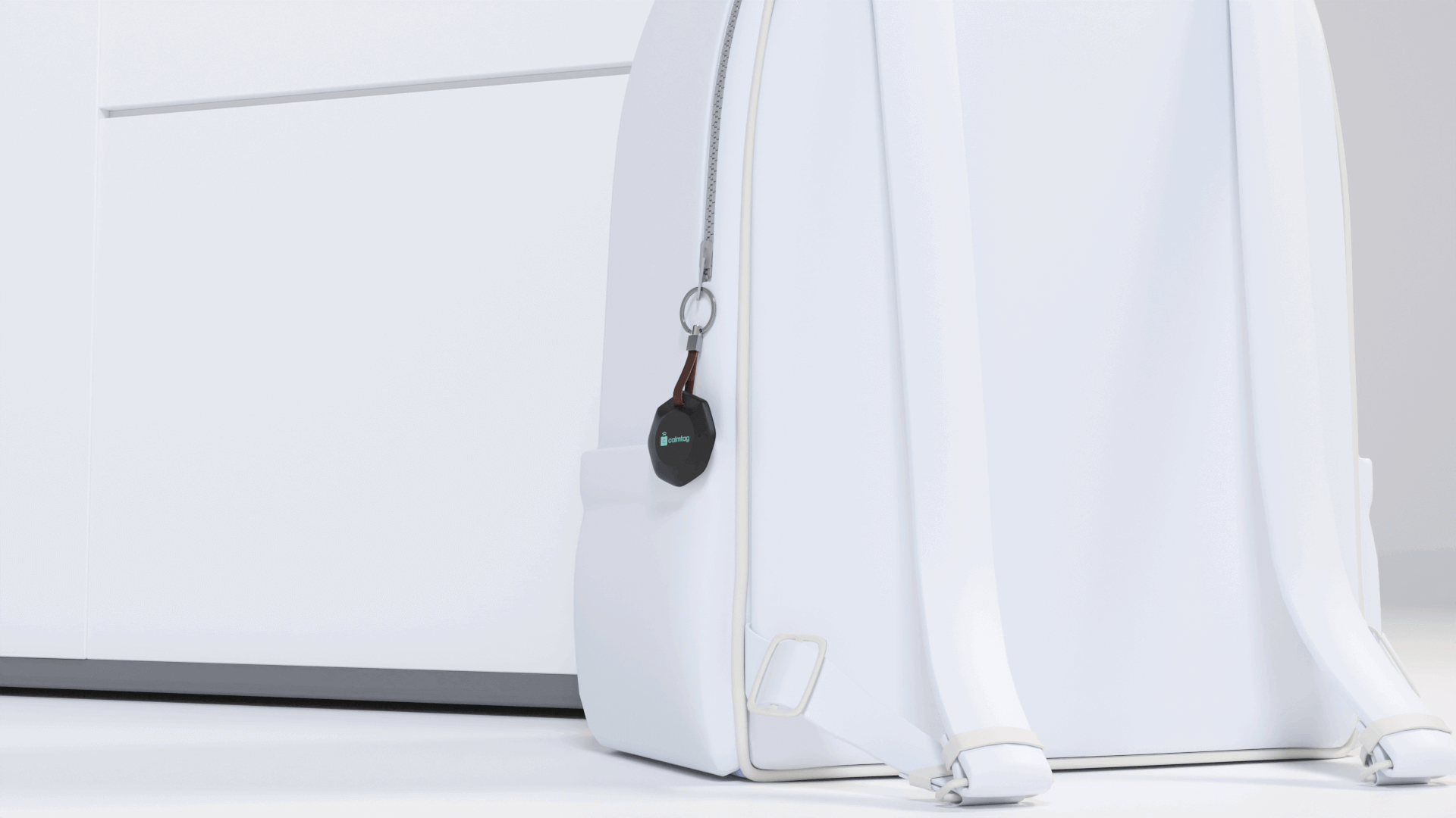
Attached to backpack — device integrated into a typical backpack zipper accessory position, demonstrating that the form factor is proportional to the accessory and does not alter the bag’s aesthetic.
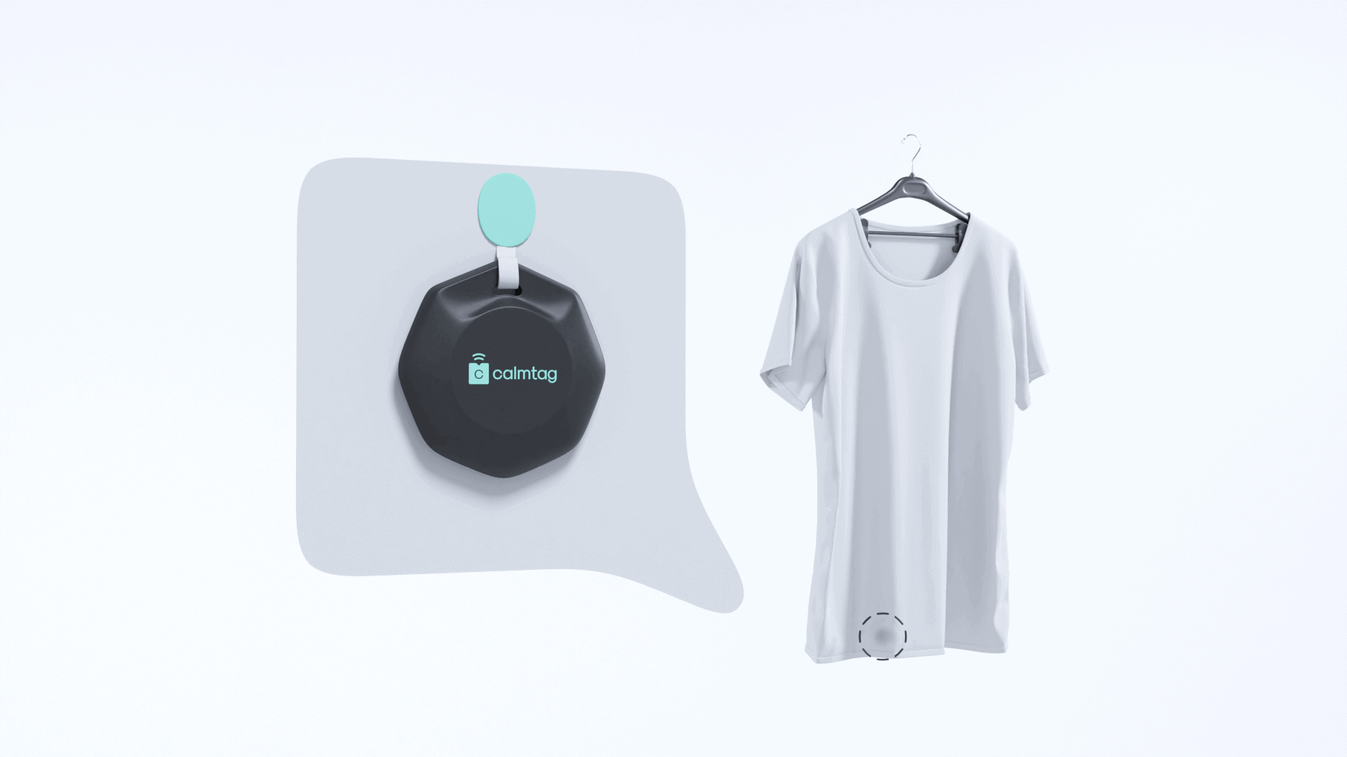
Integrated with clothing — device attached to a jacket chest pocket or waistband clip position, showing the depth profile and how the attachment system holds the device flush against the fabric.
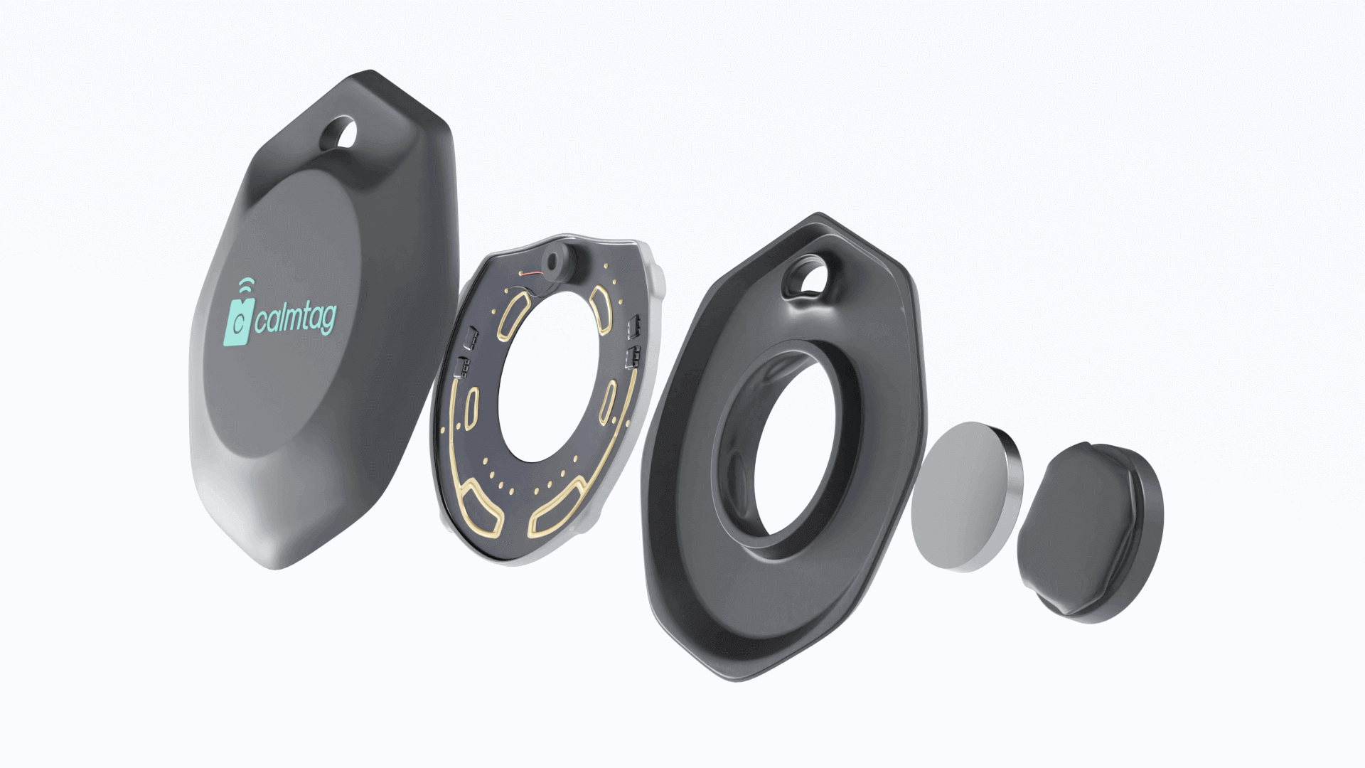
Exploded assembly render — shows the internal component stack, the housing halves, the attachment rail system, and all fastener positions. This render is the primary handoff document for the manufacturing partner.
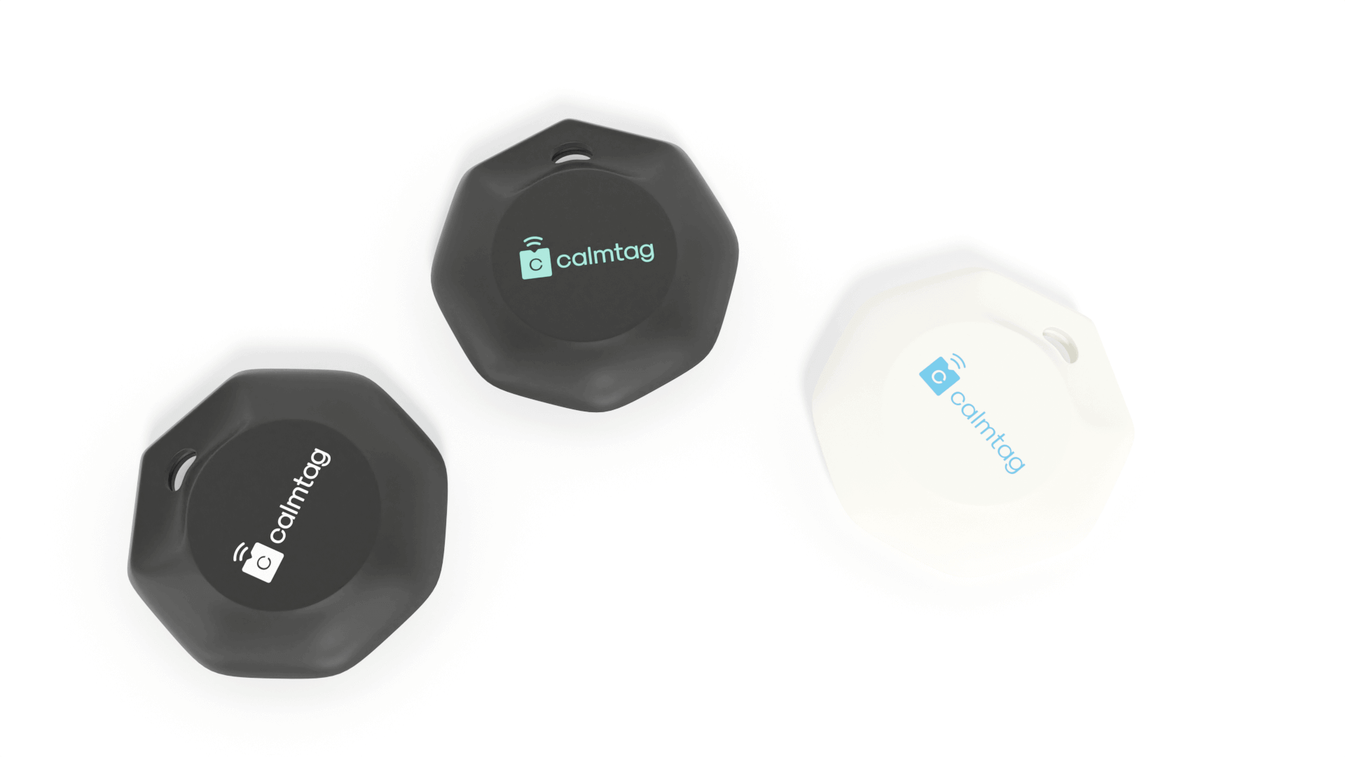
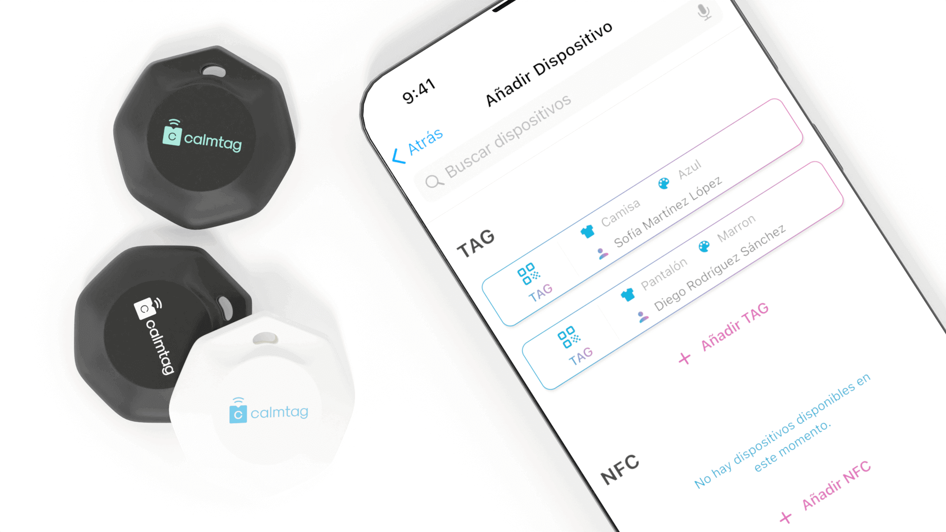
Colour variants — three colourways (black, white, slate grey) rendered to production colour specification, allowing brand and marketing teams to select without a physical sample.
Technology Applications
The product design methodology Maedcore applied to Calmtag is the same process used for any embedded hardware enclosure:
Industrial sensor housings. GPS modules, environmental sensors, and IoT communication hardware all have the same RF clearance and sealed-enclosure requirements as the Calmtag device. The DFM process Maedcore follows produces housings that go from CAD to tooling without design iteration at the manufacturing stage.
Ruggedised field devices. The multi-attachment system design — interchangeable accessories on a common rail — is a pattern applicable to field devices that need to mount to multiple surface types (pipes, rails, wall panels, clothing).
Embedded hardware product development. Maedcore’s process from component layout to photorealistic manufacturing-handoff renders covers the complete product design lifecycle for any hardware product requiring custom enclosure development.
Technologies Used
Project developed with: IoT Device Design — GPS Module Integration — 3D Modelling — DFM Engineering — Enclosure Engineering — Injection Moulding Preparation — Photorealistic Rendering — Embedded Hardware Product Design
Need a Custom Enclosure or Hardware Product Design?
Maedcore takes embedded hardware products from component specification through DFM-validated CAD to manufacturing-ready deliverables. If you need an IoT device, industrial sensor housing, or any custom electronic enclosure designed for production, request a design consultation.
Request Design Consultation | View Mechatronics Services | See All Success Stories
Further Reading
Further reading: our guide to the best 3D modelling software in 2026 and the most impactful AI applications for business in 2026.
About the Author
Eduardo Fuentevilla Blanco
Robotics Engineer
For over a decade, I have been driven by a single mission: leveraging AI and robotics to build a world of automated production. I believe that by creating self-sufficient systems, we can empower people to refocus on what truly matters—their families and their passions. My expertise spans from winning prestigious European startup competitions to architecting complex, integrated hardware and software projects. I specialize in bridging the gap between today's industrial challenges and tomorrow's autonomous solutions.
Ready to transform your company?
Book a free 30-minute meeting with an engineer.